Deer Feeder Indicator
DESCRIPTION:
Deer hunting as a means of survival or as a sport dates back thousands of years and as a means of obtaining meat for survival dates back to pre-history. Many types of deer are hunted all over the world. Methods of pursuing deer and other game are almost always subject to some government regulations. Each state has its own set of rules and regulations on how deer and game can be pursued and hunted. The duration of the hunting season is often based on the population and health of the deer herd. The number of hunters expected to participate is estimated, and that is often a factor in the regulations.
Many methods of pursuing deer are applied by various hunters. Preparation is one of the most important methods to apply for a successful hunt. A successful hunter may scout areas they plan to hunt for several months before the deer season opens. Trail or game cameras are often utilized in the location that shows signs of recent deer activity. The cameras using infrared or flash photography are set up in active areas and are triggered by heat or motion and can give the deer hunters an excellent idea of the hunting situation.
Planting food in an active deer area is a technique used by many hunters depending on the regulation of that particular state or region. Setting up feeders that will automatically distribute corn or oats into an active deer area will attract the animals and make changes in their feeding patterns. Deer feeders can range from some simple home- made versions to sophisticated and automated feeders. The feeders are commonly available in most outdoor retailers or online stores. The typical feeder usually consists of a bin or hopper that will contain the feed and a small distribution unit is located at the base of the feeder. The unit is typically gravity fed and is designed to distribute a set amount of feed. Deer learn to feed at these stations and keeping the feeder full of food can be a particular problem for a hunter. The bin or hopper will last only a certain amount of time and the device must regularly be visited in order to keep the container well stocked. There is usually no way to know how much feed has been used until the owner physically visits the site and checks the supply.
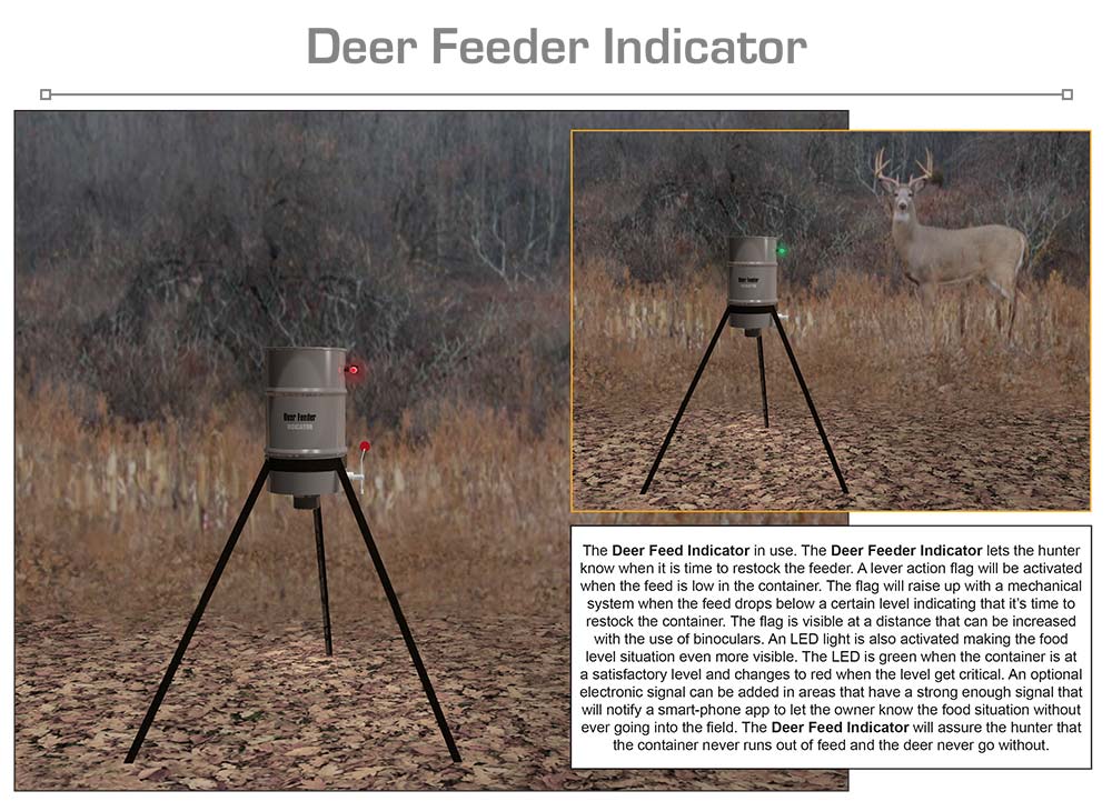
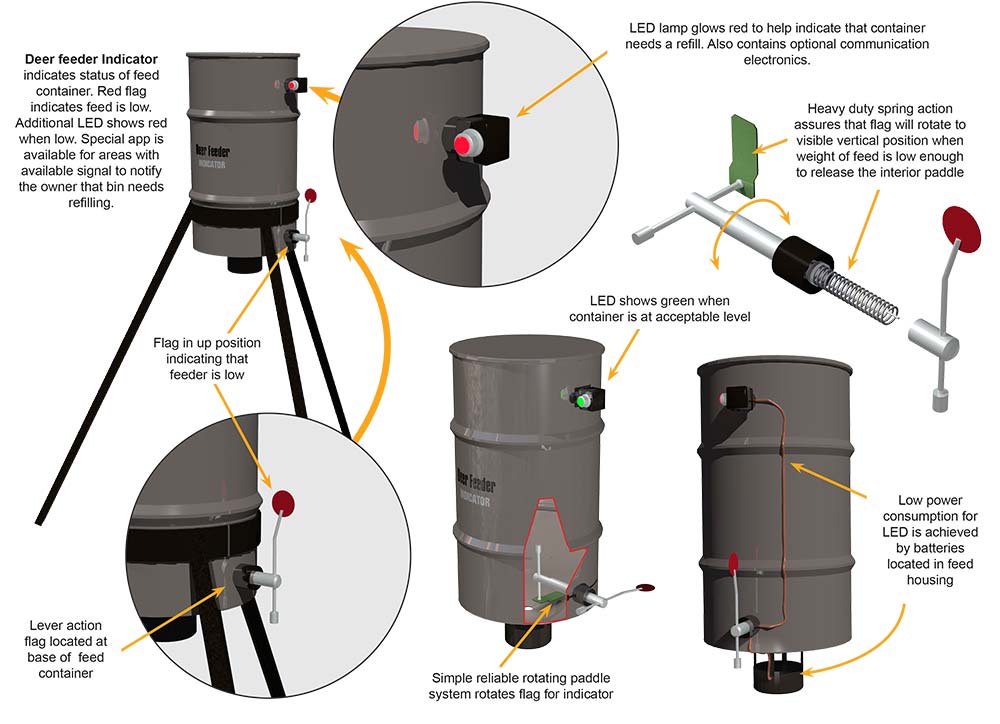
The Deer Feeder Indicator is an innovative and unique solution to keeping a deer feeder well stocked with food. Consisting of a reliable and straightforward lever and spring loaded paddle and flag system the Deer Feeder Indicator will let the hunter know the status of the container of feed at a distance. The interior of the system contains a paddle that is activated by the weight of the feed in the container. The paddle is connected to a spring-loaded shaft. When the feed gets low, the weight of the deer feed in the container is no longer sufficient to keep the paddle depressed. The shaft will rotate. powered by the internal spring to an upright position. The opposite end of the shaft outside of the container has a red metal flag that will be visible at a distance. The use of binoculars can enhance the distance the flag is visible. The Deer Feeder Indicator will reduce or eliminate the amount of time it takes to walk the distance to the feeding station to check the status of the feed container. As an additional enhancement to the visible flag system an LED lamp is electronically connected to the base of the rotating shaft. Once the shaft is rotated to the upright and visible position, indicated by the low level of feed in the container the red LED lamp is activated. The LED lamp is visible in low light situations where the flag may not be as discernable. As an additional option, an electronic signal can be activated and connected to a smart-phone app to give the user an even greater ability to check the status of the feed container. The Deer Feeder Indicator will prevent the constant checking of the feed status and eliminate wasted time and effort in the field.
SPECIFIC, UNIQUE FUNCTIONS OF INVENTION:
- Deer feed status can be checked at a distance
- Reliable mechanical system
- LED adds more visibility
- Spring loaded rotation
- Green LED indicates status of feed is good
- Red LED indicates low feed status
- Works with different types of feeding stations
- Smart-phone app available for off-site status
- Rugged construction
PRODUCT COMPONENT CLARIFICATION:
The “Deer Feeder Indicator” is an innovative hunting accessory product that has been designed to be added to an existing deer feeder and show the internal grain/pellet level without having to approach the feeder, remove the lid, and peer inside. The indicator has two modes of level indication. One is the external arm with the red circular end that is raised when the internal food level is nearing empty, and two, the red or green LEDs in the electronic module near the top of feeder where green indicates an acceptable level inside and red indicates it is nearing empty. There is an LED on each side of the module, which can be observed with binoculars over hundreds of feet. Both of these indicators work in tandem and automatically change state when the feeder is refilled.
Currently, the automatic deer feeders work on timers that engage the spin or protein pellet tube feeders. These typically are operated to feed 3 or 4 times a day, dropping 1 to 2 pounds of feed per time. One schedule suggested by a feeder manufacturer is 6-hour increments with one feeding in the middle of the night. Many others are used as the hunter adjusts the feeding schedule to attract the der and grow the optimum sized antlers possible. The feeders typically hold from 30 to 55 gallons of feed and have to be filled regularly during the feeding season. The common way to determine the level of feed is to create an empirical schedule and verify the re-fill rate by going to each feeder, climbing up, removing the lid, and peering inside. If it needs re-filling, the hunter can do so at that time, marking down the day and calculating when they should return to re-fill. Miscalculations or inability to return on the fill day can cause an interruption in feeding, which can cause loss of interest by the deer, and reducing the effectiveness of the feeding operation, causing many other problems for the hunter during the deer season.
The “Deer Feeder Indicator” resolves almost all of these problems by providing an after-market product that can be added to the existing feeder, which allows observation of the internal food level from long distances. A drive by on an ATV at several hundred feet, rather than having to visit and climb each feeder, is much more time and labor effective. If the feeder needs to be refilled, the indicator shows this at approximately the 15% level, allowing the hunter a day or two to re-fill the feeder. The indicator automatically resets itself when the feed is added, so there is no additional labor required to establish a full condition.
- As an option: While the product is described as an after-market product herein, it could be supplied as part of the feeder when it is shipped from the manufacturer (an OEM improvement to the feeder).
The “Deer Feeder Indicator” consists of 3 basic components and is supplied with the appropriate drill bits, hole saw, templates, fasteners, and detailed instructions as part of the system, dramatically improving the installation. The system components are, but not limited to, the following.
The electronic module: This module is fabricated using several commercially available components mounted in the extremely durable housing. These are, but not limited to, the following.
- The housing: This housing is injection molded from polycarbonate plastic. This plastic is very durable, resists drop shocks, is highly resistant to rodent gnawing, and is often used in this type of application. The housing will be molded using black plastic to improve the contrast for the LED projecting light out of either side of the housing. The back of the housing has a molded in and polarized connector that locks onto the connecting cable from the arm switch and has reinforced mounting holes for the supplied fasteners. The sealed housing also protects the internal electronics from the elements.
- The PCB: This printed circuit board (PCB) is fabricated to the final assembler’s requirements in a world class contract electronic assembler facility. The standard thickness, double sided FR4 circuit board material is populated with surface mounted components where possible. Any through-hole devices are inserted after the surface mounted assembly, soldering, and cleaning. The circuit board is designed to have all the components oriented so they can be mounted with the LED illuminators projecting out of the protective lenses mounted in the housings. After assembly, the PCBs are protected with a moisture adsorption preventive conformal coating.
- The microcontroller: This very low power micro-computer is mounted on the PCB and employs solid state memory for the program changing the red/green LED state. The computer also is supplied with a Bluetooth capability so the operation program can be upgraded if required during its operating life.
- The LEDs: These are low power, super bright illuminators. They are red when the current runs through in one direction and green when the current runs through in the other direction. There are 2 LEDs, one on each side of the housing, facing 180° from each other. These bright LEDs are recessed in the black housing and are visible from several hundred feet when the observer is within a 60° solid angle.
- The application: This app allows communication with the electronic module if its software needs upgrading. The communication can take place using any smartphone, tablet, or laptop computer.
- The Solar Cell: The solar cell is a 3” square unit that puts out 5 V at 100 mA and is glued into the housing using silicone adhesive. This solar cell will fully charge the battery from 25% in about 4 hours, allowing for fully charging in a day even if it is cloudy or stormy. The solar cell is tilted at 30° to allow northern hemisphere light to impinge directly and allow water, snow, or ice to slough off as rapidly as possible.
- The rechargeable battery: This nickel cadmium (NiCad) battery is made with 4 AAA batteries wired together. This makes a 4.8V battery pack at 600 mAHr capability. The microcomputer’s program allows it to deep cycle to about 25% and then recharge to lengthen its useful product life.
Indicator arm: This arm is manufactured using 316 alloy stainless steel rod. The rod is cut to length on a CNC milling center and is drilled and tapped as required in the same operation. The rods screw into the end pieces and the indicator/drive support arms are screwed into the connecting rods. The connecting rods are pinned into the couplings of the gear box. The outside shaft of the indicator arm shaft is threaded with Acme threads and an Acme nut holds the indicator shaft securely in the side of the feeder enclosure. The side of the flange has two protrusions that force themselves into the side of the hole cut with the supplied hole saw, preventing it from turning during use.
The gear box and the interior flange are tack welded together to prevent turning and a 30° movement on the inside (drive) arm turns the outer (indicator) arm 90°. The torsion spring in the interior (drive) shaft returns the drive arm to 60° from horizontal when the feed level is equal to about 15%. The switch mounted on gear box is engaged when the outer arm is vertical and the polarized cable carries the signal to the LED enclosure. The end of the drive arm has a rectangular plate pinned to it and the outer arm has a round red painted disc pinned to it. The red disc is vertical when the feeder housing is at 15% full and is horizontal when the feeder is refilled.
Connecting cable: This polarized cable is fabricated with a flexible sheath. This cable is a 2 wire 18- gauge copper stranded wire with SJOW insulating jacket, making it a good cable for this application. The supplied wire is terminated with polarized locking connectors and is supplied in a length that will run from the indicator arm to the electronic enclosure whether the system is deployed on a smaller or 55-gallon feeder. The oil and water-resistant cable will not be affected by the oil from the grain/feed or any water that may seep into the feeder. The insulation is also highly resistant to abrasion and is installed inside the feeder so it is protected from rodent gnawing.
The Deer Feeder Indicator is designed to be aesthetic and effective in the application. The relative ease of manufacture and the moderately inexpensive components provide good marketability for the manufacturer. The user benefits from improved internal feed level indication and remote determination of this level, which should provide considerable market interest in the product.
The invention is illustrated in the following drawings of the essential points as explained to us in the documentation.
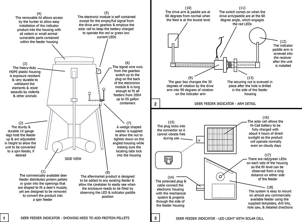
Drawing 1, Block 1: Deer Feeder Indicator – Showing Need To Add Protein Pellets
(1) The commercially available deer feeder distributes protein pellets or grain into openings that are shaped to fit a deer’s muzzle, yet are designed to be removed to convert the product into a spin feeder.
(2) The sturdy and durable 14-gauge legs hold the feeder up and are adjustable in height to allow the unit to be converted to a spin feeder, if desired. The tripod legs allow for stable support even on uneven ground.
(3) The heavy-duty HDPE plastic housing is exposure resistant and very durable to withstand the elements and resists assaults by rodents and other animals.
(4) The removable lid allows easy access by the hunter to allow easy installation of the indicator product into the housing with all rodent or small animal vulnerable parts contained within the feeder housing.
(5) The electronic module is self contained except for the empty/full signal from the drive arm gearbox and employs a solar cell to keep the battery charged to operated the red or green low current LEDs.
(6) The signal wire runs from the gearbox switch up to the plug on the back of the electronics module and it is long enough to fit all feeders from 200# up to 55 gallon containers.
(7) The wedge shaped washer is supplied to allow the nut to tighten down on the angled housing while making sure the locating tables lock into the housing. This washer is not used on straight sided feeders.
(8) The aftermarket product is designed to be added to any existing feeder and allow the caretaker to easily see when the enclosure needs to be filled by observing the LED and indicator paddle position.
Drawing 1, Block 2: Deer Feeder Indicator – Arm Detail
(9) The gearbox changes the 30 degrees of rotation by the drive arm into 90 degrees of rotation on the indicator arm.
(10) The drive arm and paddle are at 60 degrees from normal when the feed is at the lowest level.
(11) The switch comes on when the drive arm/paddle are at the 60 degree angle, which engages the red LEDs.
(12) The indicator paddle arm is screwed into the receiver after the unit is installed.
(13) The securing nut is screwed in place after the hole is drilled in the side of the feeder housing.
Drawing 1, Block 3: Deer Feeder Indicator – LED Light With Solar Cell
(14) The polarized plug and cable connect the electronic housing with the mechanical system and projects through the side of the feeder housing.
(15) The plug locks into the connector so it cannot vibrate free during use.
(16) The solar cell allows the Ni-Cad battery to be fully charged with about 4 hours of direct sunlight so the product will operate normally even on cloudy days.
(17) There are red/green LEDs on each side of the housing so the fill level can be observed from a long distance on either side of the feeder.
(18) The system is easy to mount on almost any commercially available feeder using the supplied templates, drill bits, hole saw, and detailed directions.
Although a single embodiment of the invention has been illustrated in the accompanying drawings and described in the above detailed description, it will be understood that the invention is not limited to the embodiment developed herein, but is capable of numerous rearrangements, modifications, substitutions of parts and elements without departing from the spirit and scope of the invention.
This document has been prepared for the manufacturer’s elucidation. The manufacturer’s decision makers should consider this product for licensing (providing intellectual property protection for their sales of the product in return for a royalty payment for a period of years) or an outright purchase of the patent for a negotiated fee. The inventor and his team are standing by to consider offers for licensing or outright purchase of the patent.