
Magnification Device
DESCRIPTION:
According to historical records, the telescope patent was submitted to the government of the Netherlands in 1608 for a refracting telescope. The actual inventor is lost to history, but its news of its existence spread throughout Europe. Galileo became aware of it and built his version in1609 and observed celestial objects utilizing the invention and making his conclusions. The light-gathering element or the “objective” was investigated soon after the introduction of the refractive telescope, and it was discovered that it could be a mirror instead of a lens. The advantage of using parabolic mirrors instead of lenses reduced the spherical and eliminated chromatic aberrations. This discovery led to many proposed designs and several attempts to build reflecting telescopes. It was not until 1668 that Isaac Newton constructed the first practical reflecting telescope. That design still bears his name as the Newtonian Reflector. The invention of the achromatic lens in 1733 corrected some of the color aberrations present in the lenses and led to more functional and shorter refracting telescopes. Reflecting telescopes eliminated the color problems associated with refracting telescopes, but mirror technology was crude, and the issue of fast tarnishing speculum metal mirrors hampered the development of reflecting telescopes. The speculum metal mirrors were replaced with the introduction of silver coated glass mirrors. The technology of reflective telescopes over refracting types became more widespread due to this improvement in mirrors. Many types of telescopes now exist, and these include radio telescopes and infrared telescopes.
The amateur and professional users of telescopes currently use both types of telescopes, but the reflecting type of device is preferred for celestial observation. The mirror used in a reflecting telescope is called a reflector. The reflector is curved and reflects light to form an image. The curved design creates a focal point within the structure of the telescope that is picked up by a seconded angled mirror and focused into a viewing lens or eyepiece. Almost all major telescopes used in astronomy currently are of the reflector type. One of the disadvantages of a reflector telescope is its inability to change its focal length coming from the static position and curve of the reflecting mirror.
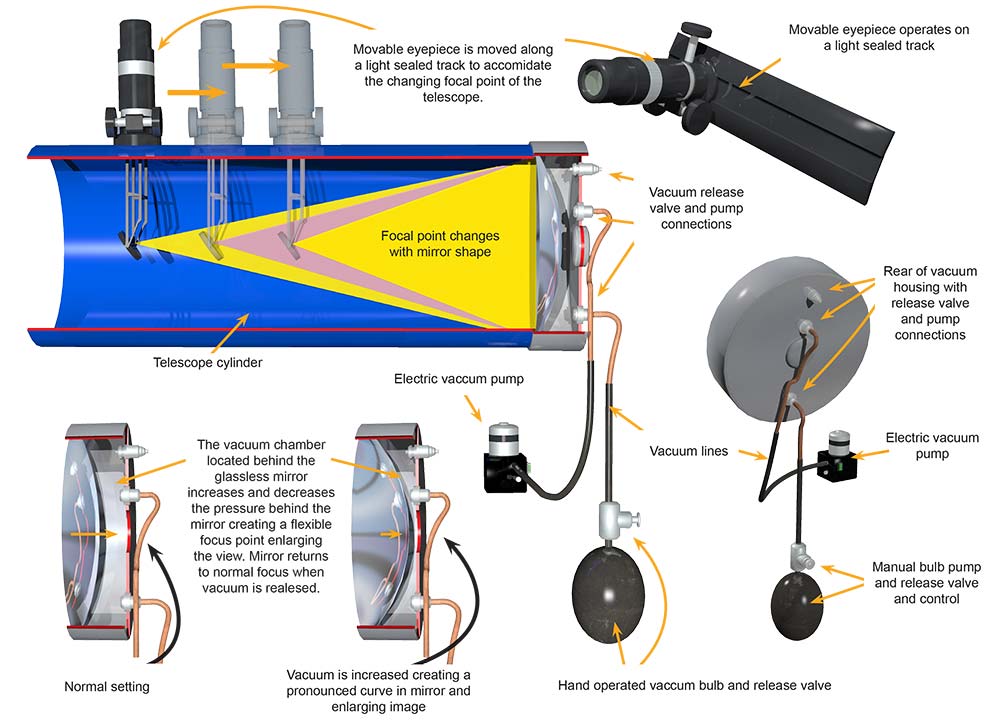
The Magnification Device is an innovative and unique product designed to bring focusing and enlargement power to images produced by a reflector telescope. The Magnification Device utilizes the flexibility and reflecting the capacity of glassless mirrors technology to enhance the productivity of persons observing objects using a reflector telescope. Consisting of a standard reflector telescope optical tube the Magnification Device replaces the static curved mirror with a flexible glassless mirror to create a focusing and enlargement environment within the telescope. A vacuum chamber is mounted in the place of the standard mirror housing. The vacuum chamber contains a flexible glassless mirror with a sealed vacuum chamber behind. The vacuum chamber has two ports connected to the back and an electric automated vacuum pump to pull air out of the vacuum chamber behind the mirror. When the vacuum increases, the curve on the mirror increases changing the focal point of the mirror and enlarging the view. The automatic electric pump is supplemented by a hand held manual pump operated by a squeeze bulb. A release valve is located above the squeeze bulb to regulate the vacuum for precise focusing. A release valve is also located on the back of the vacuum chamber for regulating the vacuum pressure and to release the vacuum to return the mirror to normal. An eyepiece is mounted on a light sealed rail on the outside of the optical tube to allow the eyepiece to move to accommodate the changing focus point of the mirror. The Magnification Device will allow the observer to change the focal length of the mirror to enlarge objects that are being viewed by the telescope operator. The Magnification Device will create a more functional and efficient telescope enabling enlargement that otherwise would be impossible with a standard reflective telescope.
SPECIFIC, UNIQUE FUNCTIONS OF INVENTION:
- Replaces static mirrors with glassless technology
- Produces enlargement of objects within the telescope
- Vacuum chamber has automatic electric vacuum pump
- Manual bulb operated pump with control valve
- Release valve located on back of vacuum chamber
- Flexible mirror changes focal length of telescope
- Movable eyepiece mounted on side of optical tube
- Creates a multi-focus telescope
- Vacuum chamber can be returned to normal viewing
PRODUCT COMPONENT CLARIFICATION:
The “Magnification Device” is an innovative telescope product that has been designed to gather light with the efficiency of a large ground glass mirror but with a significant savings in weight. The flexible glass mirror is about 7 mils thick and operated by pulling a vacuum on the back side of the mirror. The larger the magnitude of the vacuum, the greater the curve of the mirror. When combined with the moveable eyepiece, which can be moved to the focal point of the vacuum adjustable mirror, and the eyepiece focus, the unit can provide the same efficiency of a standard telescope while weighing and costing much less.
Currently, the standard telescope employs a large and thick polished glass mirror. This part of the telescope is fixed and eyepiece focus is moved to discriminate any selected object. This mirror is heavy and with the mounting hardware, contributes a lot of weight to the telescope. Grinding a ‘perfect’ curve is also difficult and then polishing can create a degradation of the curved surface.
The “Magnification Device” resolves almost all of these problems by using a very thin, lightweight, yet quite durable front surface mirror. This semi-flexible material’s curve can be adjusted using a vacuum pulled on the backside of the mirror. This vacuum, combined with the ambient atmospheric pressure applied to the front surface of the mirror, forces it into a sharper curve as the vacuum level is increased. The user can control this using either the battery powered pump or the fine control hand bulb. After the session is over, the vacuum can be released using the vacuum release fitting. Then the optical tube cap can be replaced over the front of the tube, and the telescope and table top tripod can be placed in the supplied carry bag. If the mirror becomes damaged, the vacuum cup can be removed from the optical tube and be returned to the manufacturer for an inexpensive mirror replacement.
The “Magnification Device” Is manufactured using several novel and some commercially available sub-components. These are, but not limited to, the following components.
The mirror: The mirror is fabricated using a fusion drawn glass that is very fine grained and is about 7 mils thick. The glass is roughly ground, fine polished, cleaned, plasma etched, and about 3-mils of vacuum vapor deposited aluminum is applied to the front surface to make the mirror. The mirror is mounted in a molded silicone rubber base that is adhesively bonded to the interior of the molded aluminum vacuum cup, sealing the mirror in place while imparting a bit of a curve to the mirror at rest. The fusion drawn glass is cut to diameter, using special cutting techniques, into circles that are then processed into mirrors. These processes are, but not limited to, the following.
- Rough finishing: The circles are placed in a 4’ diameter orbital head carrier and are spun on bed of microfiber cloth using a slurry of suspended 3-micron diamonds in water. The rounds are processed in the slurry for 5 minutes. After processing, the rounds are cleaned in an ultrasonic cleaner and rinsed in deionized water.
- Fine finishing: The circles are placed in a 4’ diameter orbital head carrier and are spun on bed of microfiber cloth using a slurry of suspended 0.5-micron cerium oxide in water. The rounds are processed in this slurry for 5 minutes. After processing, the rounds are cleaned in an ultrasonic cleaner and rinsed in deionized water.
- After drying, the cleaned rounds are placed in a vacuum chamber, are plasma etched, and then approximately 3-mils of aluminum is deposited on the front surface to make the mirror with about 94% reflectance, while retaining its normal flexibility so it can be shaped by the vacuum.
As an option, there are other materials that can be used as the flexible, glassless mirror. These are, but not limited to, the following.
- 5-mil thick polyester film that has been front surface metalized with a 3-mil coating of aluminum. This has from 86% to 92% reflectivity.
- 5-mil thick polyethylene terephthalate (PET) film that has been front surface metalized with a 3-mil coating of aluminum. This has from 86% to 92% reflectivity.
- 5-mil thick polyamide film that has been front surface metalized with a 3-mil coating of aluminum. This has from 88% to 92% reflectivity.
The vacuum cup: This piece is molten metal molded in a permanent mold using A380 alloy aluminum. The molten metal is forced into a permanent mold and after cooling the mold is opened to provide the part. The sprues are cleaned off and the part is sent to a CNC milling center for cleanup and finishing. The threads for the vacuum fittings are tapped using this machine. After machining, the part is cleaned, anodized, and dyed. After finishing, the vacuum fittings with the Buna-N O-rings are installed and the mirror with the silicone rubber base rings are installed in the cup, and the cup is force fit on the end of the optical tube until it seats against the dead stop. The vacuum cup is supplied with the following commercially available pumps and valves.
- The vacuum release valve allows the user to release all or some of the vacuum to change the shape of the mirror. At the end of the session, the vacuum can all be released so the mirror returns to the at rest condition, which has a small (large radius) curve to it.
- The battery powered vacuum pump allows the user to make quick and larger changes in in the vacuum resulting in large changes in the curvature of the mirror.
- The hand pump allows the user to make fine curvature changes by making small changes in the vacuum in the cup behind the mirror.
The optical barrel: This barrel is made using a commercially available, lightweight, yet strong, extruded aluminum tube. The tube is cut to length using a CNC lathe, then transferred to a CNC milling center where the optical track insert is cut and mounting holes drilled and tapped. After machining, the part is cleaned, anodized, and dyed. Then the end of the barrel is covered with a plastic end cap to keep dust, dirt, and debris out of the barrel during storage or transportation.
The aluminum sub-components can be anodized and dyed in almost any vibrant color, so a distinctive color, or colors, may be chosen to enhance the product recognition factor, which can dramatically improve the market adoption of the product. These are, but not limited to, the following.
| Standard Colors | ||
|---|---|---|
| Black | Gray | Bronze |
| Gold | Royal Blue | Navy Blue |
| Purple | Red | Green |
| Teal | Orange | Pink |
| Turquoise | Clear (Silver) |
The eyepiece: The commercially available eyepiece assembly is supplied with 3 different lenses. These are 1.25” diameter standard Plossl 4-element lenses at 6mm, 12.5mm, and 20 mm. These lenses can be exchanged to achieve the optimum performance from the product. The geared focus allows the user to finely adjust the eyepiece until all is clear and then the gear ratio holds the eyepiece at the focus point until the user moves it. The eyepiece mirror is mounted at 45° on a specially fabricated frame that integrated to the bottom of the eyepiece.
The optical track: The top of the magnifier is fitted a plastic track that is screwed to the aluminum optical barrel. This track assembly is injection molded using polypropylene plastic and consists of a slide in tracks that hold the eyepiece and then 2 collapsible side curtains that move with the eyepiece to prevent any light leakage as the eyepiece is moved up and down the barrel to find the mirrors focal point.
The Magnification Device is designed to be aesthetic and effective in the application. The relative ease of manufacture and the moderately inexpensive components provide good marketability for the manufacturer. The user benefits from improved use while reducing the weight and less expensive mirror replacement, which should provide considerable market interest in the product.
The invention is illustrated in the following drawings of the essential points as explained to us in the documentation.

Drawing 1, Block 1: Magnification Device – Assembly Detail
(1) The eyepiece is supplied with focus knobs to allow fine adjustment of focus to accommodate the variation in lens flexing when the vacuum is applied to the back side of the mirror.
(2) The magnifier is supplied with several eyepieces to allow tailoring the product to provide the optimum focus and magnification at each adjustment in vacuum.
(3) The open end of the magnifier is covered with a tight fitting plastic cap to keep any dust, dirt, and debris out of the optical barrel during storage or transport.
(4) The eyepiece slides along the optical focus track to achieve the optimum clarity after the mirror is bent using the externally applied vacuum.
(5) The optical track is sealed to prevent any light intrusion into the aluminum barrel of the device except that gathered through the front opening of the tube.
(6) Vacuum release fitting. This is a commercially available device.
(7) Electrical vacuum pump fitting. This is used for large changes in curvature.
(8) Manual vacuum pump fitting. This is used for fine control of the change in curvature.
(9) Glass mirror safety stop. This prevents the mirror from contacting the fittings and braking it in the event that the battery powered pump is left on inadvertently.
(10) The aluminum end cap is sealed using standard vacuum practices and fittings, which then allows the user to pull a vacuum, curving the mirror into a tighter radius and moving the focal point to change the magnification.
(11) The flexible mirror is made from fusion drawn glass in a very thin cross section allowing for reasonable flexing for this application, even after the vacuum vapor deposited front surface plating and the polished glass reflects images with very little distortion.
(12) The eyepiece mirror is angled at 45 degrees and projects the image gathered at the focal point of the flexible mirror and projects it upward into the eyepiece lenses so the user can see the image. The magnification can be finely tuned by swapping eyepiece lenses and using the focus knobs for the optimum in image clarity.
a. As an option: a 5-piece eyepiece lens set and a 5-piece optical filter set, that screw onto the top of the eyepiece lenses, can be supplied rather than the 3 standard eyepiece lens.
Although a single embodiment of the invention has been illustrated in the accompanying drawings and described in the above detailed description, it will be understood that the invention is not limited to the embodiment developed herein, but is capable of numerous rearrangements, modifications, substitutions of parts and elements without departing from the spirit and scope of the invention.
This document has been prepared for the manufacturer’s elucidation. The manufacturer’s decision makers should consider this product for licensing (providing intellectual property protection for their sales of the product in return for a royalty payment for a period of years) or an outright purchase of the patent for a negotiated fee. The inventor and his team are standing by to consider offers for licensing or outright purchase of the patent.