Mechanical Tire Lift
DESCRIPTION:
Construction and transportation that maintains the economic viability of the world depends on heavy equipment. Heavy equipment moves earth, lifts beams, paves roads, and serves many other aspects of our constantly moving and building society. Humans have always been builders and movers. When the building and moving becomes large in scale machines are constructed to take the heavy loads that are impossible for humans to manipulate. Trucks and other vehicles deliver foodstuffs in huge quantities that feed and nourish millions of people around the globe. Heavy equipment helps build and construct the roads and infrastructure. All of the transportation and heavy construction and moving equipment depend of the basic invention of the wheel. The wheel is responsible for most of the advancement in services performed by the many machines and vehicles that everyone depends on to keep civilization going. Many of the wheels that service the commerce of the world involves the use of tires to roll on. The wheel when coupled with a tire on heavy equipment can become a considerable issue when service is required. Service technicians are required to remove, replace or repair damaged or worn wheels and tires. Removing wheels from heavy equipment or trucks requires that the weight of the vehicle be removed from the wheel and tire so that it can be removed and serviced. Jack and lifts are used to lift the equipment of the ground to gain access to the wheel and tire that requires service.
With the equipment raised off the ground the service technician can begin the process of removing the wheel and tire for whatever service it may require. In many cases the tremendous weight of the wheel and tire on heavy equipment can become a serious problem for the technician. The bulk and weight is dangerous and the work is fatiguing. Manual labor removing the wheel and tire can require several technicians or improvised resources such as forklifts or other equipment that is not designed for such a job.
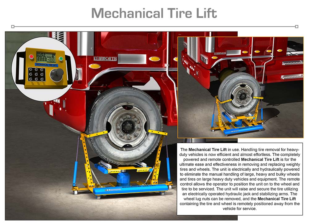
The Mechanical Tire Lift is a unique and innovative product that removes the manual labor required to lift and remove tires and wheels from heavy equipment and trucks. Constructed of high-quality materials the Mechanical Tire Lift can remove a great deal of the heavy lifting that is required when servicing the tires and wheels of automobiles or trucks. The Mechanical Tire Lift is designed to operate by remote control and all of its functions are powered either by electric or hydraulic operations The Mechanical Tire Lift is simply positioned by remote control under the mounted wheel and tire and quickly adjusted to secure the wheel and tire by utilizing a roller platform that is adjusted in height by a hydraulic jack that is power operated. Two steel rollers located on the top of the unit make contact with the tire and allow the tire to rotate while still mounted to the vehicle. This enables the technician access to all of the wheel lugs by easily rotating the wheel and tire. Powered steel adjustable brackets located on the side of the Mechanical Tire Lift secure the tire and prevent movement of the wheel and tire after the wheel lugs are removed. This arrangement allows the full weight of the wheel and tire to be carried by the Mechanical Tire Lift. Once the wheel and tire are loose from the vehicle the Mechanical Tire Lift can be positioned away from the vehicle utilizing the power drive to the wheels and controlled by the remote unit. The wheel and tire can now have whatever service is required performed on them. The procedure is performed in reverse when re-mounting the tire and wheel on the vehicle. When utilizing the Mechanical Tire Lift the technician will never have to bear the weight of the wheel and tire when removing or replacing them.
SPECIFIC, UNIQUE FUNCTIONS OF INVENTION:
- Allows wheels and tires to be easily removed/replaced from a vehicle
- Operated with a wireless remote control
- All movement functions are powered
- Rotates wheel on rollers for access to wheels lugs
- Powered adjustable rollers for different size tires
- Adjusts in height using powered hydraulic jack components
- Powered adjustable steel side brackets for securing wheel and tire to the unit.
- Tire brackets are adjustable by the control unit
- Takes entire weight of wheel and tire
- Eliminates having to lift wheel and tire to mount or remove
- Saves service technician from physical injury or strain
- Heavy duty casters and powered drive wheels allow movement of wheel and tire
once removed from automobile - High-quality materials give product long service life
PRODUCT COMPONENT CLARIFICATION:
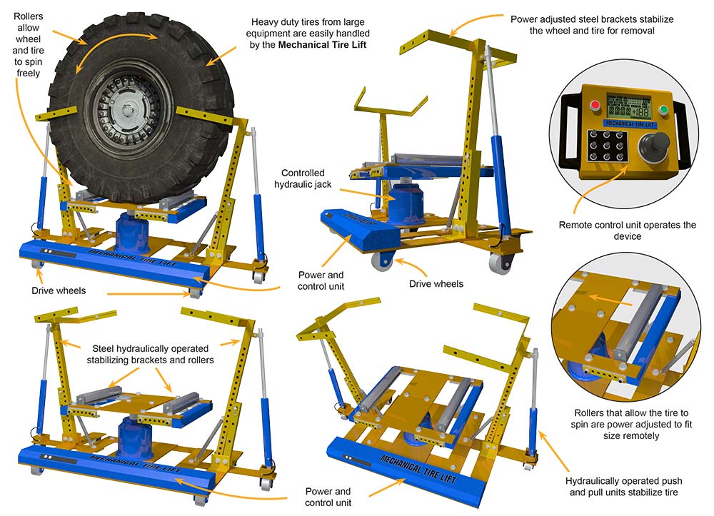
The “Mechanical Tire Lift” is an innovative maintenance product that has been designed to capture, remove, replace, and minutely position a heavy-duty wheel and tire for easy re-installation without involving lifting by the technician. The hydraulic and DC electrically powered product is mounted on a steel frame with 3 wheels where 2 are fixed and non-driven and 1 is steerable and driven to move the product. The main jack and roller stand raises and lowers the wheel/tire for height positioning, while the side supports and guides hold the tire erect. The product is remotely controlled, dramatically reducing any lifting the tire technician has to perform and greatly reducing strains or fatigue.
Currently, the tire technician loosens the nut or studs and then jacks the vehicle up. They finish removing the studs/nuts and then lift the wheel/tire off the hub. The wheel/tire combinations of a commercial truck can weigh up to 215 pounds. So … either more than one technician is required to lift the tire onto a dolly or some mechanical aid for the single technician is required. After the tire is removed, repaired or replaced, and re-mounted on the wheel, the wheel/tire must be reinstalled on the vehicle. Getting it positioned so the studs line up can be a real chore, even if the tire is on a dolly and the vehicle can be raised and lowered incrementally. Having to replace the wheel/tire in the gravel parking lot or in the field for farm or industrial equipment just further exacerbates the problem and can lead to severe back, leg, or arm strain to the technician.
The “Mechanical tire Lift” resolves most of these problems by providing a method to support and micro-position the wheel/tire without requiring any lifting effort by the technician. Once the vehicle is jacked up and the nuts or studs are loosened, the product is driven up to the vehicle and positioned directly under the wheel/tire. Then the rollers are raised to capture the wheel/tire from below, the side supports are positioned to allow the guided to capture the tire so it will not fall over, and the roller moved in or out to provide the optimum lift for the wheel/tire combination. Then the product and the wheel/tire are driven to the tire removal and repair station. This series of complex motions is performed remotely using a ruggedized tablet for control and the WTM application.
After the tire is repaired or replaced and mounted on the wheel, it is replaced on the product and then driven over to the vehicle. Using the fine controls in the application, the wheel/tire is micro-positioned and manually spun so the lugs/studs line up and the wheel/tire is secured to the vehicle. After the wheel/tire is installed, the product is readjusted to release the wheel/tire and driven back to the charging station, where it waits for the next use. The amount of technician effort is greatly reduced, making the task much easier to accomplish with virtually no fatigue.
The “Mechanical Tire Lift” is fabricated from many different components, some of which are commercially available and are integrated into the assembly. There are, but not limited to, as follows.
The frame: The base of the machine is fabricated from 0.5” thick cold rolled steel plate. The steel is cut to shape from sheet stock using the water jet machining center. All the bolt holes and openings are formed in this operation. Various small parts are also cut from this 0.5” thick sheet stock, like the side support hinge plates and the double acting cylinder mounts. The frame is then placed in a jig and robotically welded to join all sections into one contiguous base and the small parts are also welded in place. After welding, the product is powder painted and thermally cured to make a scratch and corrosion resistant surface.
The support tubes: These adjustable steel square tubes are cut to length and have the holes cut in the water jet machining center. The larger outer tube accepts the slightly smaller interior tube and both have mating holes that align and accept the quick release pin to adjust the height of the guides. The lower support tubes are drilled to accept hardened steel bolts allowing the support arms and guides to be moved in or out under control by the double acting cylinders, which are controlled by the tablet working with the onboard computer.
The tire guides: These guides are formed using 1” wide by 0.25” thick steel bars, which are formed into 14” wide by 6” deep U channels. These channels are welded onto the upper support tube with the U opening toward the center of the product. The 14” wide guides will accommodate almost any tire including over the road wheels and tires, most farm tires except rear tractor tires, and many industrial wheels/tires like skid steer units.
- As an option: The guides can be fabricated to be adjustable in width. The back section is drilled to accept 2 bolts that retain the U shape while allowing the guides to be adjusted in width.
Painting: The steel components can be supplied in almost any vibrant color, so a distinctive color may be chosen to enhance the product recognition factor, which can dramatically improve the market adoption of the product.
The fixed wheels: These steel wheeled fixed casters with sealed, pre-lubricated bearings. The casters and wheels are galvanized to prevent rust and corrosion. Each caster is capable of supporting up to 675 pounds with a large safely margin. The combination of the 2 steel wheeled casters and the steerable drive wheel allows the product to be driven forward and backward to the optimum position to mount or dismount the wheel/tire.
The drive wheel: This all terrain, urethane rubber coated, steel drive wheel is steerable and variable speed to allow easy positioning of the product. The DC drive motor runs on the 18V battery as does the steering motor. Both of these are operated in conjunction under on-board computer control. The product can translate quickly between the vehicle and the tire repair station or can move minutely to position wheel/tire in optimum location. The steerable wheel is capable of rotating ±90° from straight back and this movement is sufficient to allow micro-positioning as required. The drive wheel is capable of supporting up to 1/3 of the 1,000 pound-maximum product load with a significant safety margin.
The hydraulic DC operated pump and reservoir: The DC operated pump is mounted in the end of the hydraulic housing which is located under the frame of the product. The DC pump maintains a 100 PSI pressure in the system and comes on when the flow requirement is engaged by the computer operating the solenoid valves to move the tire guides or raise or lower the jack assembly. The fluid flows out of or back through the solenoid valves as required and is retained in the reservoir. The reservoir has a sight glass that allows the user to observe the fluid level in the reservoir when the system is at rest.
The double acting guide cylinders: These commercially available cylinders are long stroke, double acting cylinders that have the capability to move the tire guides and the wheel/tire to insure proper sitting on the rollers on the jack. The controlling computer utilizes optical position sensors in the lower pin area to determine the angle so the tire guides are positioned at similar angles on each side, insuring the wheel/tire is positioned in a center location on the rollers.
The center support jack: This commercially available, double acting hydraulic jack has a lift stroke of 12.5” and will lift a load of 16,000 pounds. This is far in excess of the typical 250-pound load expected with OTR wheels/tires. The heavy-duty jacks are made for frequent commercial use. The ram is nickel-plated for corrosion resistance and smooth operation against the seals. The double action allows for fine positional control through the use of the tablet working in conjunction with the on- board controlling computer.
The roller separation drive: The roller separation drive is a central bi-directional DC motor upon which Acme ball screws are mounted. The ball nuts are mounted in steel slides that move in or out as the motor is turned. The drive employs 2 different screws, a left and a right-handed ball screw to move the ball nuts in or out when the motor turns. There are 2 drive units, one on each side of the roller end, and they are synchronized to keep the rollers parallel. The 13” wide steel rollers with sealed, pre- lubricated bearings are capable of supporting 575 pounds each. Having the wheel/tire on the rollers allows the technician to easily rotate it to align the studs/lugs for installation after it is micro- positioned with the product.
The controlling computer: The onboard computer is fabricated to control the hydraulic and DC electric motors to perform the movement functions of the device. This ruggedized computer is placed in a sealed housing under the steel frame. The Bluetooth 4.0 and 802.11ac WiFi data access provides excellent and reliable uptime and the proprietary operating program allows macro and micro positioning. The controlling computer is supplied with, but not limited to, the following.
| Product Description | Specification |
|---|---|
| Processor | Intel Atom 1.44 GHz with turbo |
| Memory | 2 GB DDR3 SDRAM 1600 MHz |
| Hard drive size | 32 GB eMMC |
| Operating system | Windows 10, 64 bit |
| Audio | DTS studio sound |
| Ports | USB type-C fast charge, USB 3.0, Mini HDMI |
| Battery | 8 AHr at 18 Vdc polymer li-Ion rechargeable |
| Wireless | 802.11ac (Miracast enabled) |
| Bluetooth | Bluetooth 4.0 |
| Charging port | Remote polarized connector at rear of frame |
The controlling tablet: This ruggedized tablet is designed to be used in the harsh shop environment. The thick rubber case and hardened touch screen is perfect for the maintenance operation. The fast 4G LTE broadband and 802.11ac WiFi data access provides excellent and reliable uptime. The tablet is supplied with, but not limited to, the following.
| Product Description | Specification |
|---|---|
| Display | 10.1” diagonal WXGA touchscreen |
| Processor | Intel Atom 1.44 GHz with turbo |
| Memory | 2 GB DDR3 SDRAM 1600 MHz |
| Hard drive size | 32 GB eMMC |
| Operating system | Windows 10, 64 bit |
| Media drive | MicroSD card reader |
| Audio | DTS studio sound |
| Video | Intel HD graphics with shared graphics memory |
| Ports | USB type-C fast charge, USB 3.0, Mini HDMI |
| Battery | 5600 mAHr polymer li-Ion rechargeable |
| Camera | 5 MP, true wide vision camera |
| Wireless | 802.11ac (Miracast enabled) |
| Bluetooth | Bluetooth 4.0 |
| Weight | 3.0 pounds | Recharging | Uses a high current Qi wireless recharging cradle |
The printed circuit boards (PCBs): The PCBs for both devices are fabricated to the final assembler’s requirements in a world class contract electronic assembler facility. The standard thickness, double sided FR4 circuit board material is populated with surface mounted components where possible. Any through-hole devices are inserted after the surface mounted assembly, soldering, and cleaning. Both circuit boards are designed to have all the components oriented so they can be mounted with the LED illuminators projecting out of the lenses mounted in the housings. After assembly, the PCBs are protected with a moisture adsorption preventive conformal coating.
The application: This operational program allows fine control over the mechanical tire lift mechanism. The finger motions and other controlling methods allow macro and micro positioning capabilities for fast and easy removal and re-installation of the wheel/tire with a minimum of required technician labor. The application is a one-time programming effort with applicable upgrades and will work with any touch screen device like a 2-in-1 computer, a tablet, or smartphone.
As an option: The frame of the product may be supplied with 2 each 18-Watt LED floodlights mounted on the frame opposite the drive wheel and projecting outward and slightly upward. These commercially available lights illuminate the workspace where the wheel/tire is mounted and the ground upon which the product is being driven. The lights are 4” square with aluminum heat dissipating housings. The 6-LED chip lighting modules project light out at a 60° angle providing a broad viewing angle for work and efficient nighttime operations. The LED lighting has a very long operating life and can easily withstand the harsh environment. The 12-volt lighting is operated by the controlling computer and is driven through a power supply operating from the 18 V battery.
The Mechanical Tire Lift is designed to be aesthetic and effective in the application. The relative ease of manufacture and the moderately inexpensive components provide good marketability for the manufacturer. The user benefits from reduced muscle stress, fatigue, and potential injury, which should provide considerable market interest in the product.
The invention is illustrated in the following drawings of the essential points as explained to us in the documentation.
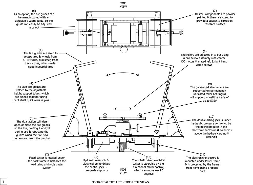
Drawing 1, Block 1: Mechanical Tire Lift – Side And Top Views
(1) Hydraulic reservoir and electrical pump drives the central jack and the guide supports.
(2) Fixed caster is located under the back frame and balances the load using a tricycle caster system. The two fixed casters and the steerable drive wheel make a stable system for travel over concrete, asphalt, gravel and even compacted dirt surfaces.
(3) The dual action cylinders open or close the tire guides on the tire, holding it upright during use and retracting the guides when the tire is to be removed from the product.
(4) The side tire guides are welded to the adjustable height support tubes, which are pinned together using bent shaft quick release pins.
(5) The tire guides are sized to accept tires and wheels from OTR trucks, skid steer, front tractor tires, and other similar sized industrial tires.
(6) As an option, the tire guides can be manufactured with an adjustable width guide, so the guide can easily be adjusted in or out.
(7) All steel components are powder painted and thermally cured to provide a scratch and corrosion resistant surface.
(8) The rollers are adjusted in and out using a ball screw assembly with center DC motors and mated left and right hand Acme screws.
(9) The galvanized steel rollers are supported on permanently lubricated roller bearings and will support wheel/tile loads of up to 575 pounds.
(10) The double acting jack is under hydraulic pressure controlled by the microcomputer in the electronic enclosure and solenoids above the hydraulic pump and reservoir.
(11) The electronic enclosure is mounted under the lower frame and is protected by the frame from things being dropped on it.
(12) The V belt driven electrical caster is steerable by the directional motor control which can move +/- 90 degrees. This makes the wiring less complicated and prevents wrapping the feed wires around the steerable wheel base.
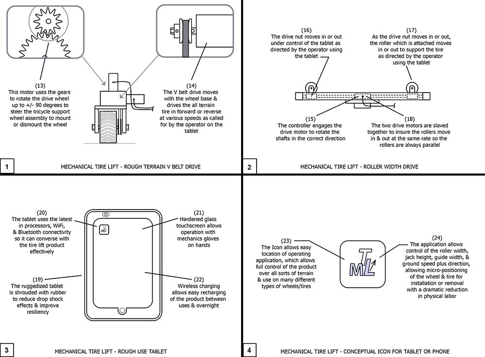
Drawing 2, Block 1: Mechanical Tire Lift – Rough Terrain V Belt Drive
(13) This motor uses the gears to rotate the drive wheel up to +/- 90 degrees to steer the tricycle support wheel assembly to mount or dismount the wheel.
(14) The V belt drive moves with the wheel base and drives the all-terrain tire in forward or reverse at various speeds as called for by the operator on the tablet.
Drawing 2, Block 2: Mechanical Tire Lift – Roller Width Drive
(15) The controller engages the drive motor to rotate the shafts in the correct direction.
(16) The drive nut moves in or out under control of the tablet as directed by the operator using the tablet. The user employs swipes, pinches, and finger placements to guide the product on the tablet. The experience is very similar to flying a drone.
(17) As the drive nut moves in or out, the roller which is attached moves in or out to support the tire as directed by the operator using the tablet.
(18) The two drive motors are slaved together to insure the rollers move in or out at the same rate so the rollers are always parallel.
Drawing 2, Block 3: Mechanical Tire Lift – Rough Use Tablet
(19) The ruggedized tablet is shrouded with rubber to reduce drop shock effects and improve resiliency.
(20) The tablet uses the latest in processors, WiFi, and Bluetooth connectivity so it can converse with tire lift product effectively.
(21) Hardened glass touchscreen allows operation even with mechanics gloves on the hands.
(22) Wireless charging allows easy recharging of the product between uses and overnight.
Drawing 2, Block 4: Mechanical Tire Lift – Conceptual Icon For Tablet Or Phone
(23) The Icon allows easy location of the operating application, which allows full control of the product over all sorts of terrain and use on many different types of wheels/tires.
(24) The application allows control of the roller width, jack height, guide width, and ground speed plus direction, allowing micro-positioning of the wheel/tire for installation or removal with a dramatic reduction in physical labor.
Although a single embodiment of the invention has been illustrated in the accompanying drawings and described in the above detailed description, it will be understood that the invention is not limited to the embodiment developed herein, but is capable of numerous rearrangements, modifications, substitutions of parts and elements without departing from the spirit and scope of the invention.
This document has been prepared for the manufacturer’s elucidation. The manufacturer’s decision makers should consider this product for licensing (providing intellectual property protection for their sales of the product in return for a royalty payment for a period of years) or an outright purchase of the patent for a negotiated fee. The inventor and his team are standing by to consider offers for licensing or outright purchase of the patent.