Side Step
DESCRIPTION:
Salons and similar businesses have an important responsibility to their clients to maintain a safe environment. No one wants to be responsible for an injury to a customer. Not only is it not good for business it can open up legal responsibilities. Someone getting hurt in an accident on the premises is a worst-case scenario.
Most salons create happy customers that leave the establishment looking great and feeling full of confidence ready to face their day. Most business owners want to be proactive about an accident that may affect both their clients and employees. Equipment that is safe and reliable is a big part of staying pre-emptive about safety in the workplace.
One of the potential places for an accident to happen is the salon chair and its foot rest. The foot rest is a necessary accouterment of the salon equipment and provides a place for the patron’s feet to rest while in an elevated position. The foot rest provides comfort to the client while at the salon. It’s very presence presents an awkward obstacle to maneuver while getting in and out of the salon chair. The foot rest by its very nature protrudes from the front of the salon chair. This position makes it very problematic to enter and leave the salon seat. Customers have to maneuver around the foot rest to get in the chair. It is even more challenging to exit the apparatus since the patron is sitting and does not have the floor to help shift their weight and maintain balance. Accidents can happen when a client does not clear the foot rest entirely and catches a foot or clothing. The horror of watching a formerly happy client tumble from a chair and onto the floor or get tangled up in the chair is unimaginable. Elderly customers and those with less agility or limited movement are even more susceptible. Removing the foot rest is not a viable option since most salon chairs have a fixed foot rest to keep the foot rest secure to the chair, preventing any movement. The foot rest is a hazard that is encountered every day in most salons and its potential as a trip risk cannot be understated.
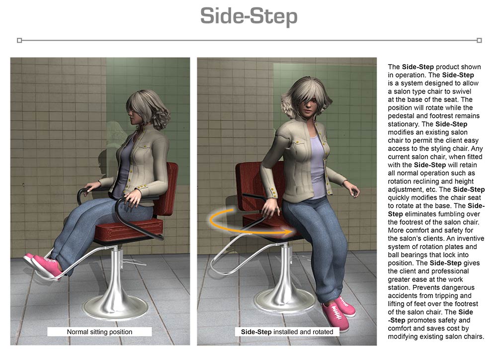
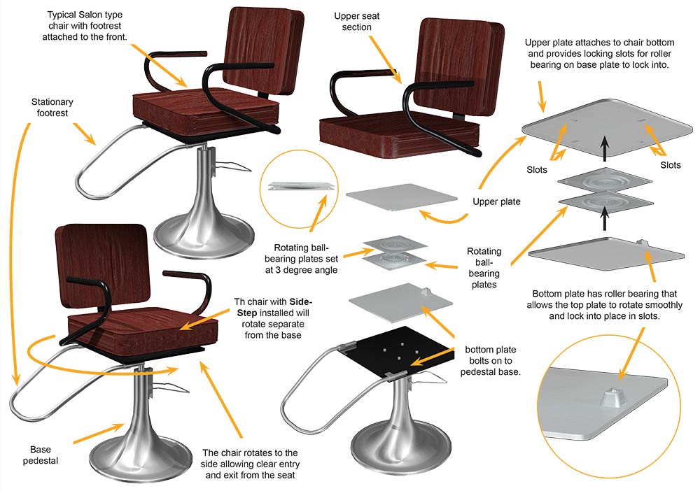
The Side-Step is an innovative and ingenious product designed to solve the issue of the foot rest being a potential liability for customers, employees and shop owners. The Side-Step is a system that retrofits existing salon equipment with a safe and easy to install alternative to the stationary foot rest. Consisting of 2 large metal plates, a dual rotating ball-bearing plate system for rotation of seat, a spring-loaded single roller bearing system for locking the seat in place the Side-Step will adapt most salon chairs. The large top plate attaches to the bottom of the seat of the chair. The rotating ball- bearing plate assembly connects to the upper plate to provide rotation of the seat. The large bottom plate connects to the lower part of the rotating ball-bearing plate assembly. On the bottom plate a single spring-loaded roller bearing assembly positioned on the upper side. This single roller-bearing assembly contacts the underside of the large upper plate. Located on the underside of the large upper plate are four slots designed to capture the single roller-bearing on the large bottom plate when rotated. This configuration will stop rotation at every 90 degrees. The slots will securely hold the seat in position. When the original pedestal locking, mechanism is engaged the seat can be returned to its original position or to one of the other positions available by gently placing pressure on the seat and the single roller-bearing will disengage and roll freely. The Side-Step provides a simple and cost effective solution to the difficulty of entering and leaving a salon chair equipped with a foot rest.
SPECIFIC, UNIQUE FUNCTIONS OF INVENTION:
- Easy to install
- Retrofits existing salon chairs
- Product can be used on both “U” shaped and “T” shaped foot rests
- Product is cost effective by saving both time and expenses
- Sturdy metal plates assure durability
- Slot in upper plate stop rotation of seat at 90-degree increments
- Safer for clients and employees
- Operates easily by hand
- Components all metal and precision made
- Eliminates tripping over foot rest
- Ease of entry and exit from salon chair
- Seat is secure when in position
- Rotates effortlessly
PRODUCT COMPONENT CLARIFICATION:
The “Side Step” is an innovative styling salon product that has been designed to allow the user to easily, and more safely, exit the stylist’s chair without tripping over the foot rest. The durable steel product allows the stylist to rotate the upper, (seating), section of the chair, which positions the foot rest at 90° to 180° from the seat of the stylist’s chair. The client can then just stand up and walk away without having to worry about the foot rest, dramatically reducing any trip hazard. The next client can walk up and sit down, whereupon the stylist rotates the chair back where the foot rest can comfortably support the feet during the styling process.
Currently, approaching the stylist’s chair can be a little disconcerting because the client must enter the chair at an angle to miss the foot rest or step upon it and turn around to sit down. When the styling is done and it the client exits the chair, the foot rest can be trip hazard, causing the client to trip, fall, or crash into the surroundings. At worst case, the client can be injured or the styling shop sued.
The “Side Step” invention resolves most of these problems by providing an easy to install interface between the support pedestal and the seating section of the styling chair. The stamped steel plates are fastened to the mating section and the chair is allowed swivel using a very strong and durable bar stool swivel. The durable, powder painted product is secured to the mating sections using the supplied stainless steel fasteners. The swivel action has ‘stops’ at the 90° locations and employ a spring loaded ball catch and a slot milled into the upper plate to achieve this function. Once the interface is installed, the operation of the chair is unaffected, except for the swivel function. The interface has a very long product life, typically longer than the chair.
The top and bottom plate: These plates are stamped from 3/16” thick cold rolled steel sheet, which is supplied to the fabricator in either 8” or 11” wide rolls. These rolls of sheet stock are fed into a flywheel press that stamps the outline and pierces the holes in the sheet. The bottom plate is formed in a progressive die to develop the ball catch holder before the holes are pierced. After fabrication, the plates are transferred to a CNC milling center for slot development and tapping operations. After machining, the plates are subjected to a vibratory deburring station, where the edges and corners are slightly rounded and any burrs from fabrication are removed. Then the plates are thoroughly cleaned, dried, and subjected to electrostatic powder paint coating. Then the coating is thermally cured to provide a very durable, scratch and corrosion resistant surface. The color chosen is not important because the product is not easily seen in normal use. However, the product can be supplied in almost any vibrant color, so a distinctive color may be chosen to enhance the product recognition factor, which can dramatically improve the market adoption of the product.
The ball catch: This catch is commercially available and is fabricated to the manufacturers outline to enhance the assembly process. The 0.5” diameter steel ball is nickel plated for durability. It is contained in brass housing that is accessed from the bottom end. In assembly, the ball is placed in the housing, the spring dropped in, and then the base is screwed in place. The ball is restricted from coming out the top of the housing and will compress completely into the housing against the spring pressure within.
The bar stool swivel: This commercially available bar stool swivel employs over 50 pre-lubricated ball bearings to support up to 350 pounds continuously and up to 400 pounds intermittently. The product is fabricated using two 1/8” thick plates that have been stamped into shape to provide the race for the ball bearings. The plates are zinc plated to prevent rust and corrosion and then are permanently assembled and riveted together. The upper and lower plates have mounting slots that accommodate from 5” to 5.5” square mounting screw hole patterns. This model also has a 3° pitch from front to back to hold the seat level as the upper half of the chair is being swiveled away from the foot rest.
In use: The salon chair is turned upside down and the base is separated from the seat by the tradesman using the appropriate tools. The lower plate is installed on the base section, the swivel is attached the lower plate, and then the swivel is attached to the upper plate installed on seat section. Then the salon chair is stood up on the base, rotated so the foot rest is off to the side, and then is ready for use.
- Other installation methods are possible and acceptable.
- Allowing the stylist to easily rotate the chair away from the foot rest gets it completely out of the way and dramatically reduces the trip hazard on standard chairs. Returning the foot rest to the support position is easily done when the client is seated by the stylist.
The Side Step is designed to be aesthetic and effective in the application. The uncomplicated fabrication and the reasonably priced components provide good marketability for the manufacturer. The user benefits from improved safety and comfort, which should provide considerable market interest in the product.
The invention is illustrated in the attached drawings of the essential points as explained to us in the documentation.
Drawing 1, Block 1: Side Step – Top And Bottom Plates, Side And Bottom Views
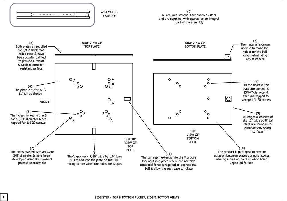
(1) The V groove is 7/16” wide by 1.0” long and is milled into the plate on the CNC milling center when the holes are tapped.
(2) The holes marked with an A are 3/8” diameter and have been developed using the flywheel press and specialty die. A hole location chart is available upon licensing.
(3) The holes marked with a B are 13/64” diameter and are tapped for 1/4-20 screws.
(4) The plate is 12” wide and 11” tall as shown.
(5) Both plates as supplied are 3/16” thick cold rolled steel and have been powder painted to provide a robust scratch and corrosion resistant surface.
(6) All required fasteners are stainless steel and are supplied, with spares, as an integral part of the assembly.
(7) The material is drawn upward to make the holder for the ball catch, eliminating any fasteners.
(8) All the holes in this plate are pierced to 13/16” diameter and are tapped to accept 1/4-20 screws.
(9) All edges and corners of the 12” wide by 8” tall plate are rounded to eliminate any sharp surfaces.
(10) The product is packaged to prevent abrasion between plates during shipping, insuring a pristine product when being unpacked for use.
(11) The ball catch extends into the V groove locking it into place where considerable
Drawing 2, Block 1: Side Step – Bar Stool Swivel And Drawn Ball Catch Holder
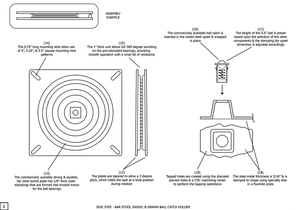
(12) The plates are tapered to allow a 3 degree pitch, which holds the seating at a level position during rotation.
(13) The commercially available strong and durable, bar stool swivel plate has 1/8” outer stampings that are formed into smooth tracks for the ball bearings.
(14) The 0.75” long mounting slots allows use of 5”, 5.25” and 5.5” square mounting hole patterns.
(15) The 1’ thick unit allows full 360 degree swiveling on the pre-lubricated bearings, providing smooth operation with a small bit of resistance.
(16) The commercially available ball catch is inserted in the raised steel upset and snapped in place.
(17) The height of the 0.5” ball is preset based upon the selection of other components and the stamping die upset is adjusted accordingly. It is important that the housing does not scrape on the upper plate during operation, yet allows the full movement of the ball into the V groove to lock in the seat position during use.
(18) The sheet metal thickness is 3/16” and is stamped to shape using specialty dies in a flywheel press.
(19) Tapped holes are created using the stamped pierced holes and a CNC machining center to perform the tapping operations.
Although a single embodiment of the invention has been illustrated in the accompanying drawings and described in the above detailed description, it will be understood that the invention is not limited to the embodiment developed herein, but is capable of numerous rearrangements, modifications, substitutions of parts and elements without departing from the spirit and scope of the invention.
This document has been prepared for the manufacturer’s elucidation. The manufacturer’s decision makers should consider this product for licensing (providing intellectual property protection for their sales of the product in return for a royalty payment for a period of years) or an outright purchase of the patent for a negotiated fee. The inventor and his team are standing by to consider offers for licensing or outright purchase of the patent.