Sliding Antenna Skid Mount
DESCRIPTION:
The cellular network of land areas called cells is serviced by at least one fixed- location transceiver. Normally three cell sites or base station transceiver stations operate in one cell area for best service connections. These base stations provide the cell network coverage that is used for the transmission of voice, data, and other functions. Joined together these base stations provide wide coverage over large land areas. Most of the inhabited areas of the earth are now covered by a cellular network of some type. The success of the mobile phone and mobile computing is a direct result of this technology. Without the modern cellular antenna array, the modern technological wonders of communication would not exist as we know it.
Cell antennas frequently use towers to mount the transceivers on for increased exposure and coverage but with the expanding use of cell phones and other devices the use of towers can become impractical. The high-density areas that need the most coverage by transceivers are the most difficult to place tall towers. The real estate needed for towers is limited and often not available. The placement of transceivers on tall buildings, water towers, and other tall structures becomes necessary for creating sufficient coverage in the high-density and high-population areas. Many owners of these structures, are open to the concept of placing the cell transmitters on their structures.
A cellular antenna mounted on a tall structure such as a building must be situated where there will be the minimum amount of obstruction of the transmissions. In many cases, this will require multiple installations to avoid any obstructions that would limit the transceivers ability to function. When a cellular antenna or transceiver is mounted on a building, it is often mounted on the roof on a frame or platform that will face outward from the structure and as near to the edge of the building as possible. The issue of placing the cellular transceiver that adjacent to the edge is getting to the devices for service or installation. Service persons working on the components will have to plan a means of gaining access to the transceivers. The devices are so close to the edge of the building that there is a hazard for persons on the ground below the devices. The service personnel must create a safety zone beneath the devices to protect the public and property. The proximity of the devices to the building structure and the height of the structure also present a hazard to the service persons working on the transceivers. The danger of a fall is always a possibility so extensive safety measures must be implemented. These safety measures take time and materials and add to the cost and can create delays of service on the cellular transceivers.
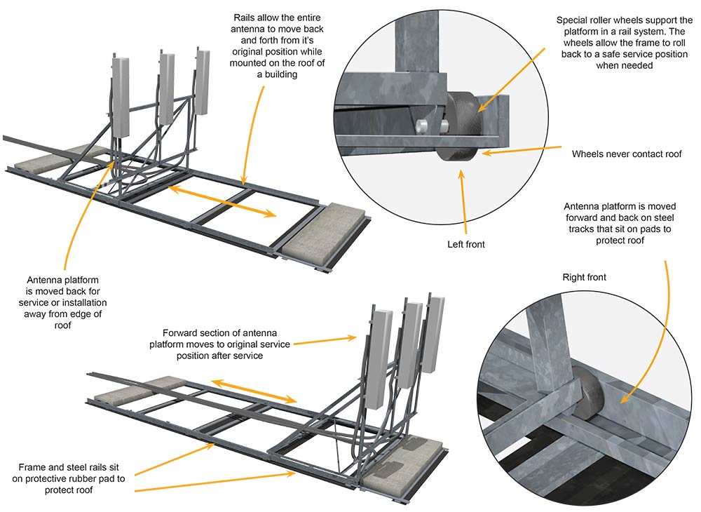
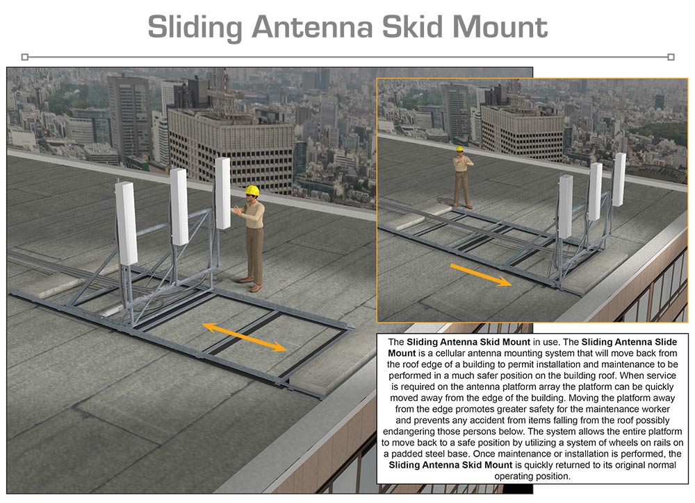
The Sliding Antenna Skid Mount is a unique and innovative solution to servicing roof mounted cellular transceivers. The unit consists of a mounting frame for the cellular transceiver and is similar to those currently in existence. The Sliding Antenna Skid Mount can also be retrofitted to an existing frame platform. The frame platform faces the cellular transceivers outward away from the building and raises them to an optimum height to clear any obstruction caused by the design of the roof. The mounting base of the platform frame contains steel rails on each side of the platform. The mounting base is fixed to the roof of the structure in the usual manner and remains stationary. The base contains the rails of the movable section that will also hold the upper structure of the platform containing the cellular transceivers. The upper section will slide out from the base utilizing several wheels at the lowest position on the platform that will allow the upper structure to roll back and forth to the edge of the roof and back to a safety position. The rails will keep the entire unit steady and permit a positive motion that is easy to control. The entire unit is supported by rubber pads underneath to protect roof. The Sliding Antenna Skid Mount will allow service personnel to move the platform frame with the mounted cellular transceivers back away from the edge of the roof into a safe position for servicing. The unit can be serviced away from the edge of the building preventing accidents and allowing normal activity on the ground below.
SPECIFIC, UNIQUE FUNCTIONS OF INVENTION:
- Allows easy access to cellular equipment
- Easily moved back from the roof edge
- Telescoping rails provide steady operation
- Wheels at base provide effortless movement
- Prevents falls and dropping of equipment or other items off of roof
- Keeps ground area underneath cellular transceivers safe
- Eliminate need for safety zones under cellular antenna mounted on building roofs
- Can be retrofitted to existing equipment
- Increases safety of service personnel
- Weather proof and easy installation
PRODUCT COMPONENT CLARIFICATION:
The “Sliding Antenna Skid Mount” is an innovative cellular infrastructure product that has been designed to easily be moved back from the edge of the roof and allow the technician to repair or replace components on the antenna mount without fear of falling off the roof or having to create an exclusion zone on the ground below the mount to prevent injury from falling components and tools. The antenna mount is similar to that currently in use except it has 2 rails underneath and utilizes smoothly operating rubber wheels that grip the T track laterally. This allows the tradesmen to pull the latch pin, then roll the antenna mount and antennas back about 6’ away from the roof edge. When the work is done, the location locking pin is pulled, the antenna mount moved back to the forward position, and then antenna mount is quickly and securely pinned in place until the next time.
Currently, the antenna mounts are often fixed on the roof top edge with the cellular antennas facing outward from the roof edge. To work on the antennas, a drop zone has to be created on the ground below so dropped tools or components are not harmful to pedestrians below the work site. Additionally, the technicians have to be careful about working the front surface of the antenna mount so they do not slip and fall off the roof, which can cause serious injuries or death. As an alternative, the counterbalance materials (concrete blocks or landscape stones) can be lifted off the back of the antenna mount and then the antenna mount and antennas moved back away from the edge of the roof. Both of these problems are labor consuming and inefficient repairs result. Additionally, because the antennas are usually positioned on the tallest buildings possible, falls can be quite injurious and litigious.
The “Sliding Antenna Skid Mount” resolves most of these problems by providing an antenna mount that rolls back away from the roof edge to allow easy setup or repair of the cellular antennas mounted on the front surface of the frame. The antenna mount system is supplied in a single bundle that can easily be transported to the roof and assembled there using a single technician. The T rails are assembled first with the spreader and the ballast plates installed. Then the preassembled trolleys are positioned on the T rails and the safety stops inserted and clipped into place. Finally, the angle iron antenna mount is assembled and bolted to the 4 trolley assemblies. After the T rail ballast stones are placed in position, the antenna is rolled to rear, and pinned into position awaiting the antenna and feed cable.
In use, the antenna position pins are pulled, the feed cable protective duct cover is opened, and the antenna is slid back while allowing the feed cable to fold back out of the duct as it moves backward. After the antenna maintenance or repair has taken place, the antenna mount is rolled forward and pinned into place, while insuring the cable is draped back into the duct as it moves forward. Being able to move the antenna mount back away from the edge of the roof allows the technician to work on the antennas without the threat of falling off the roof and no exclusion zone needs to be made on the ground below. This results in more efficient maintenance and provides a significantly safer work area.
The antenna mount frame: This mount is fabricated using A-36 intermediate tensile strength carbon steel components throughout. It is supplied to the purchaser, and thence on to the job site, with all the components and fasteners in one bundle with assembly instructions. There are 4 major components as part of the fabrication.
- Angle iron: Much of the framework is assembled using 1.5” by 0.25” thick wall angle iron. The angle iron is cut to length using a robotically controlled rotary saw from optimized length lengths of stock. After cutting to length, the bars are transferred to a robotically controlled drilling station, where the through-bolt holes are drilled. The 2 reinforcing sections are fabricated the same way, then placed in a jig and robotically welded. After fabrication, the angle iron parts are deburred, cleaned, powder painted, and thermally cured.
- T rail: This rail is the roof top rail component upon which the rubber wheeled trolleys ride. 3.0” tall with 0.25” thick riser by 2.5” wide T rail is supplied from the metal supplier to the specified length (anticipated to be 12’ each). They rest upon the rubber roof coating protective sheet that is laid down upon the flat roof prior to setting or assembling the sliding antenna mount system and are maintained parallel with the supplied 3/16” thick alignment spacer bolted between the rails upon assembly. The 2 T rails are machined on a CNC milling center to provide all the holes required to allow bolting together and installation of the receiver and hitch pins. 2 each, 90° angled end counterbalance plates are supplied for the aft end of each T rail with the bundle of materials. These plates allow easy stacking of purchased counterbalance materials, while allowing plenty of room for the 6” by 6” hinged duct to be run down the center of the system to protect the antenna feed cables.
- As an option: The T rails can be supplied in shorter sections that can be bolted together on site, rather than be supplied in the standard 12’ lengths. In that case, the additional connectors and fasteners are added to the bill of materials and the assembly instructions altered accordingly.
- The rubber tired trolleys: The T rail employs 4 steel mounting plate and urethane rubber tired trolleys that snugly fit over the upper part of the T rail and roll smoothly fore and aft as required by the technician. The steel plates are cut to shape on a computer controlled water jet machining center. The urethane rubber wheels are molded to shape and have permanently sealed bearings to insure a long product life in the field. During erection in the roof, the trolley’s 1/4” steel mounting plates are bolted to the bottom of the antenna mount frame using the supplied stainless steel fasteners. After assembly to the moving antenna mount section, the positioning pin is inserted through the antenna frame down through the T rail and is secured with the hitch pin so it cannot be dislodged.
- The safety stops and positioning pins: These are commercially available receiver hitch pins with cotter key (hitch) clips. The hardened 5/8” diameter pins are capable of withstanding up to 12,000 pound shear forces without degradation. The hitch clips remain in place until removed by the technician regardless of the weather, dust, dirt, vibration, etc.
- The protective rubber mat: This rubber mat is sized to fit under the complete system and is roughly 48” wide by 150” long. This rubber is formulated to protect rooftop coatings when used on non-penetrating satellite roof mounts. The mat is fabricated from rebonded rubber and is 1/8” thick. 1 mat is sent per sliding antenna mount system.
Paint: The steel components are to be powder painted and thermally cured. The paint can be supplied in almost any vibrant color, so a distinctive color may be chosen to enhance the product recognition factor, which can dramatically improve the market adoption of the product. The powder paint with thermal cure provides a very durable surface that is scratch resistant while being rust and corrosion resistant. It is the best for this type of application.
- As an option: The steel components can be supplied with a hot zinc coating. This silver coating works well for outdoor applications when a specific color is not required.
The Sliding Antenna Skid Mount is designed to be aesthetic and effective in the application. The ease of manufacture and the relatively inexpensive components provide good marketability for the manufacturer. The technician benefits from improved safety and more efficient installation or repairs, which should provide considerable market interest in the product.
The invention is illustrated in the four drawings of the essential points as explained to us in the documentation.

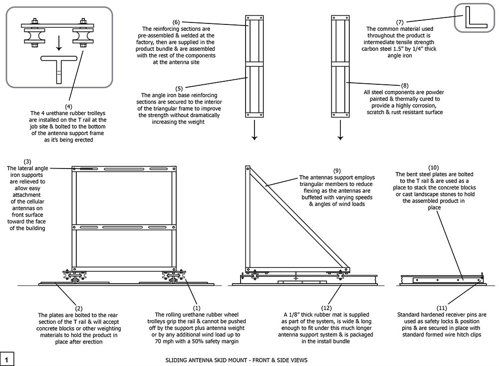
Drawing 1, Block 1: Sliding Antenna Skid Mount – Front And Side Views
(1) The rolling urethane rubber wheel trolleys grip the rail and cannot be pushed off by the support plus antenna weight or by any additional wind load up to 70 mph with a 50% safety margin. The wind load calculation also includes the wind load from 2 standard cellular antennas.
(2) The plates are bolted to the rear section of the T rail and will accept concrete blocks or other weighting material to hold the product in place after erection. The T rails are kept parallel by the C shaped spacer bolted below the front antenna location.
a. As an option, an aft spacer plate can be supplied to insure the T rails remain parallel over the full length. The aft spacer plate can take the place of the interior ballast plate in that case.
(3) The lateral angel iron supports are relieved to allow easy attachment of the cellular antennas on the front surface toward the face of the building. When the antenna mount is in the retracted position, there is approximately 6’ of roof space between the mount and the roof edge for the technician’s use.
(4) The 4 urethane rubber trolleys are installed on the T rail at the job site and bolted to the bottom of the antenna support frame as its being erected.
(5) The angle iron base reinforcing sections are secured to the interior triangular frame to improve the strength without dramatically increasing the weight.
(6) The reinforcing sections are pre-assembled and welded at the factory, then are supplied in the product bundle and are assembled with the rest of the components at the antenna site.
(7) The common material used throughout the product is intermediate tensile strength carbon steel 1.5” by 1/4” thick angle iron.
(8) All steel components are powder painted and thermally cured to provide a highly corrosion, scratch, and rust resistant surface.
(9) The antenna support employs triangular members to reduce flexing as the antennas are buffeted with varying speeds and angles of winds. The rubber wheels absorb shocks without compressing significantly so the antennas are actually more still than when rigidly mounted on the standard antenna mount.
(10) The bent steel plates are bolted to the T rail and are used as a place to stack the concrete blocks or cast landscape stones to hold the assembled product in place.
(11) Standard hardened receiver pins are used as safety locks and position pins and are secured in place with standard formed wire hitch clips.
(12) A 1/8” thick rubber mat is supplied as part of the system, is wide and long enough to fit under this much longer antenna support system and is packaged in the install bundle.
Although a single embodiment of the invention has been illustrated in the accompanying drawings and described in the above detailed description, it will be understood that the invention is not limited to the embodiment developed herein, but is capable of numerous rearrangements, modifications, substitutions of parts and elements without departing from the spirit and scope of the invention.
This document has been prepared for the manufacturer’s elucidation. The manufacturer’s decision makers should consider this product for licensing (providing intellectual property protection for their sales of the product in return for a royalty payment for a period of years) or an outright purchase of the patent for a negotiated fee. The inventor and his team are standing by to consider offers for licensing or outright purchase of the patent.


